

[Repair Case] 2016 BMW 316Li engine 3-cylinder misfire
Posted by Tony Brown on
A few days ago, a 2016 BMW 316Li was sent here by our friends for maintenance. This car is equipped with an N13 engine, and has two fault codes: cylinder No.3 misfire detected and cylinder No.3 injection device off. The ignition coil, spark plugs, and injectors have all been replaced, and the engine has also been disassembled. It is said that a valve is bent and should be replaced, but the problem remains still as the cylinder No.3 misfire. They had already tested the cylinder pressure, and there’s no significant difference between the 4 cylinders, all around 1100kPa.
During the repair they found that if one camshaft position sensor was unplugged, and the engine operated normailly. After an invalid replace of the CVVT execution solenoid valve, they came to me for help. Since the cylinder pressure had been tested, I used a self-made cylinder pressure sensor to collect the pressure waveforms of cylinders 1 and 3 at idle speed. Cylinder No.3’s waveform in valve lift control mode is as shown in Figure 1.
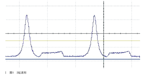
Figure 1
Cylinder No.2’s waveform in throttle mode is as shown in Figure 2.
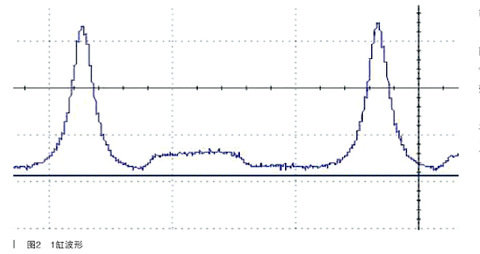
Figure 2
Comparison of the two pictures’ working states resulted in no obvious abnormality. Since the VVT’s participation or not depends on the valve opening and closing points, it is challenging to see whether the opening and closing of the cylinder No.3 is normal. The only difference is that one has the upturn when the exhaust valve is closed, and the other doesn't.
At this point in the failure analysis, it can be seen that one of the throttle modes and the electronic valve lift mode is normal and the other is abnormal. The difference between the two is the changes in valve lift. The valve train of the BMW models consists of a fully variable valve lift control (electronic valve control) and an adjustable camshaft control (twin cam variable timing), so that the closing moment of the intake valve can be freely selected. Valve lift control is performed only on the intake side, and camshaft control is performed on both the intake side and the exhaust side.
Only when the following parameters are controllable, load control without throttle can be carried out: ① the valve lift of the intake valve; ② the camshaft adjustment device of the intake and exhaust camshafts. When equipped with an electronic valve control system, the electric throttle valve adjuster and the so-called throttle mode are controlled for the following functions:
Vehicle start (warm-up process)
Idle speed control
full load operation
emergency operation
In all other operating conditions, DME operation and valve lift control mode, the throttle valve is opened until only a slight vacuum is produced. This vacuum is required if the fuel tank is vented. In the event of a malfunction, the valve lift is opened as far as possible. Air delivery is then regulated via the throttle. If the current position of the eccentric shaft cannot be detected, the valve is opened maximally without adjustment (controlled emergency operation). To achieve the correct degree of valve opening, all tolerances in the valve train must be compensated for by adjustment. During this adjustment process, the mechanical limit of the eccentric shaft is adjusted.
Therefore, the car does not pull out the camshaft position sensor, and the system is in two states: one is the throttle mode, and the other is the valve lift control mode. The biggest difference between the two is that the lifts of the valve are not the same.
Via an electrically adjustable eccentric shaft, the influence of the camshaft on the cam pushrod can be changed via an intermediate lever. This produces a variable valve lift. Carefully study the middle push rod. The lower contour of the push rod is divided into left and right parts. The left half is relatively straight, and the right half is a slope. Different parts of the eccentric wheel of the eccentric shaft are pressed on the bearing on the upper part of the middle push rod, which causes the valve to shake. The change of the contact point between the arm bearing and the lower part of the push rod is left or right, the middle push rod swings left and right, and the lower left part is relatively flat, so the valve does not move. When the valve rocker arm touches the slope position, the valve begins to open. Since the shape of the cam is certain, and the distance of the push rod swinging left and right is also certain, thus the valve lift is small when the initial position is left, and the valve lift is large when it is right.
Let's go back and look at the failure of this car. Why is the cylinder pressure normal, fuel injection and ignition normal, but the results in throttle mode and valve lift mode are not the same? The biggest difference between the two states is the maximum lift of the former and the minimum lift of the latter. Will there be a valve that does not open at the minimum lift?
In three generations of electronic valve lift control systems, BMW introduced a concept of phasing. Torque can be adjusted very quickly and accurately by means of a fully variable valve train. Adjustments in the lower valve travel range are supported by so-called phasing. At this time, the intake valve of a certain cylinder is opened synchronously by a maximum of 0.2mm. Valve 1 starts to advance from this stroke. Therefore valve 2 opens with a slight delay and catches up with valve 1 at about 6mm of travel. Then the two valves continue to open simultaneously.
Phasing is achieved by the different shapes of the two eccentrics on the eccentric shaft of the cylinder. This opening characteristic facilitates the entry of gas into the cylinder. By keeping the intake valve opening cross-section small, the flow velocity can be significantly increased with the same intake air volume. In conjunction with the geometry of the upper region of the combustion chamber, this flow rate helps the intake mixture to mix more efficiently.
In the lower part-load region, a lift deviation of up to 1.8 mm is created between the two intake valves, so that the intake of fresh air is agitated and rotated. If one valve does not open at the minimum valve lift, although there is air entering the cylinder, but the rotation is not enough, the fuel cannot form a better combustible mixture, and the mixture concentration between the spark plug electrodes is not correct, resulting in difficulty in combustion. Next is how we find the reason.
Remove the valve cover and the torsion spring, take out the middle push rod, and take off the valve rocker arm. Measure the distance from the top to the top of the valve stem directly with a vernier caliper. It is found that the No. 6 intake valve is about 0.30mm higher than the No. 5 intake valve. Other valves have no volume. Note that the original cylinder pressure is also normal, but the original valve is bent, and the seat ring is reamed. Therefore, it is believed that the hinge of the No. 6 valve causes the upward movement of the valve stem.
Remove the cylinder head, how to check the phasing next? How to check the synchronization relationship of valve opening? After a little brainstorming, I adjusted the motor to the minimum limit position, and found a problem, all the intake valves did not work, and then adjusted the motor back a few times, the No. 1, No. 3, No. 5, No. 7 valves started to work, so Mechanical minimum limit position and valve minimum lift position are two different concepts.
Use two dial indicators to hold the valves respectively. When the No. 6 valve starts to work, the opening degree of the No. 5 valve is 2.2, and when the No. 2, No. 4, and No. 8 valves of other cylinders are opened, No. 1, No. 3, No. 7 The valve opening is 1.6, so the typical 6th valve opens late. Why does valve 6 open late? As shown in Figure 3.
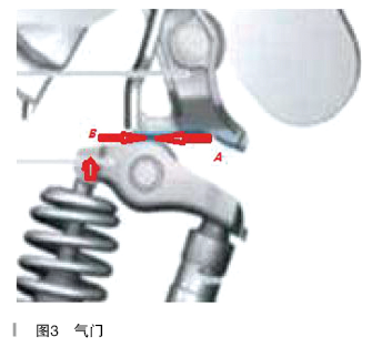
Figure 3
The upward movement of the valve stem will inevitably cause the contact surface of the rocker arm bearing and the intermediate push rod to move from point A to point B, so the lift of the No. 6 valve is reduced, and it does not even open at the minimum valve lift. The problem again, the valve seat is too hinged, how to save it? Tried switching to a middle putter with a rating of 3, to no avail. Check valve synchronization is wrong. So, I decisively replace the dismantled cylinder head assembly.
Yet another episode where the real cause of the glitch at the start was found, also a man-made glitch. After the cylinder head is installed, the car still lacks 3 cylinders, but it is different from the original one. No matter it is the throttle mode or the valve control mode, all of them lack fire. Observed here, put the ignition coil, cylinder 2 and cylinder 3 upside down each other, everything is back to normal. Carefully observe the ignition coil plug, the ignition coils of the 3rd and 4th cylinders are fake, and the 3rd cylinder sometimes has poor contact.
Therefore, it is presumed that the initial failure of the car is that the 3-cylinder ignition coil is not in good contact, resulting in a misfire. The person who repaired the outside before said the valve is bent, because the cylinder pressure is also good at the beginning, and the valve is hinged, and the cylinder head is scrapped. This is the reason!
Share this post


![[Repair Case] Audi Q5 cruise control system is unavailable](http://autospecialtools.com/cdn/shop/articles/q5_02_480x480_d8b1cb76-049c-4069-9331-81bf449c6755_400x.webp?v=1656052131)
![[Repair Case] 2019 Volvo XC60 airbag light alarm](http://autospecialtools.com/cdn/shop/articles/Volvo_01_480x480_247435e0-6338-4c79-a414-e058c1ad289e_400x.webp?v=1656051208)
![[Repair Case] 2021 Mercedes-Benz GLA200 instrument prompts "auxiliary battery failure"](http://autospecialtools.com/cdn/shop/articles/image2_400x.png?v=1656051178)
![[Repair Case] 2019 Audi uses a 3D printer to make an Audi e-tron gearbox installation](http://autospecialtools.com/cdn/shop/articles/image1_400x.png?v=1656051124)
![[Repair Case] 2018 Mercedes-Benz E300 instrument prompts "Blind Spot Assist System Stops Working"](http://autospecialtools.com/cdn/shop/articles/2022-5-24-E300_400x.png?v=1656050897)
![[Repair Case] 2019 Audi A3 cruise control function fails](http://autospecialtools.com/cdn/shopifycloud/shopify/assets/no-image-2048-5e88c1b20e087fb7bbe9a3771824e743c244f437e4f8ba93bbf7b11b53f7824c_400x.gif)